
2 月 . 17, 2025 19:40 Back to list
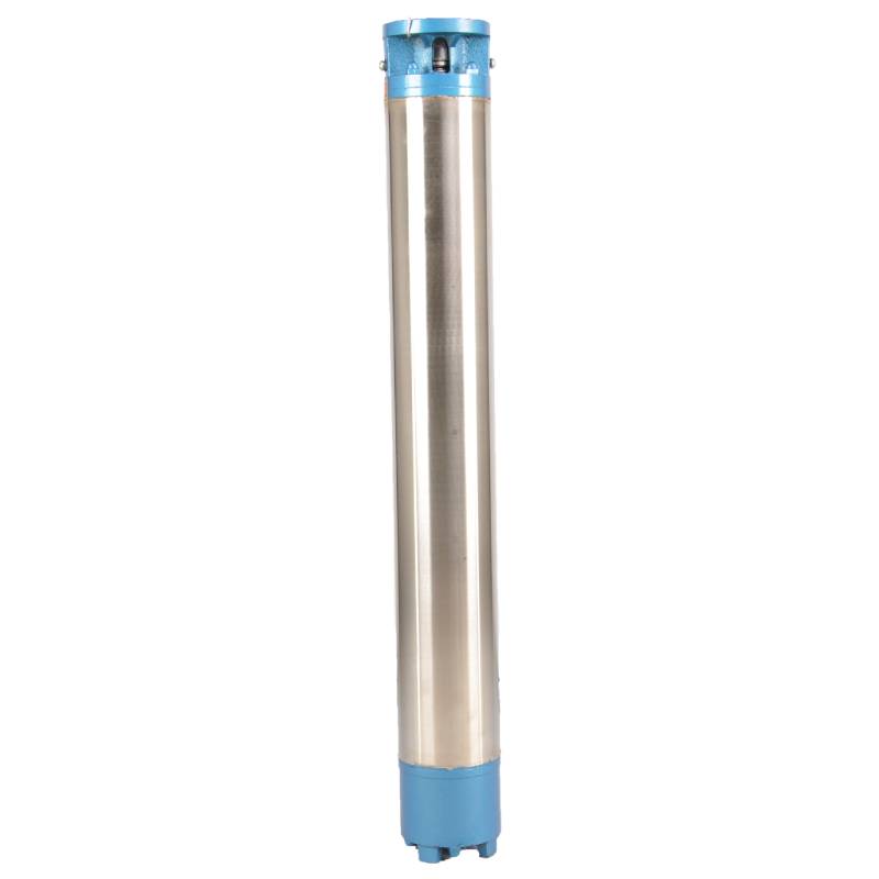
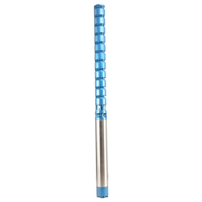
deep well submersible pump installation diagram
The integration and installation of a 3 phase submersible pump can significantly enhance fluid-handling capabilities in various industrial, agricultural, and residential settings. As an essential component of your water management system, understanding the wiring diagram of such a pump is crucial for ensuring optimal performance, safety, and maintenance.
The inclusion of protective devices in the wiring setup cannot be overstated. Circuit breakers and overload relays are vital for safeguarding the pump against voltage irregularities and overheating. These devices should be strategically placed and configured in accordance with the wiring diagram. Overload relays, installed within the circuit, will interrupt power if the motor is subjected to excessive load, providing an essential safeguard synonymous with reliability and safety. Grounding is a mandatory and critical aspect of installing a 3 phase submersible pump. Ground wires should maintain a continuous connection from the pump to the grounding point of the power source. This practice effectively mitigates potential electric shocks and enhances overall system safety. Using high-quality, corrosion-resistant connectors and ensuring all connections are tightly secured will further augment the system's safety and performance. Real-world knowledge and expertise are paramount when handling the wiring installation of a 3 phase submersible pump. Missteps can lead to poor pump performance and risk of electrical hazards. Thus, engaging with or consulting industry professionals is advisable. With diligent planning, precise integration, and regular maintenance based on the wiring diagram’s reference, these pumps will deliver efficient, powerful, and reliable service across their operational lifespan. Consider scheduling regular inspections and maintenance checks to ensure the wiring and all components remain in optimal condition, maximizing the pump’s longevity and functionality. By understanding the critical components of a 3 phase submersible pump wiring diagram and the relationship between its parts, users can foster a system that is not only efficient but also safe and durable. Prioritize learning and consultation to achieve a seamlessly operational setup, as the cumulative benefits in performance and safety are substantial when proper wiring practices are employed.
The inclusion of protective devices in the wiring setup cannot be overstated. Circuit breakers and overload relays are vital for safeguarding the pump against voltage irregularities and overheating. These devices should be strategically placed and configured in accordance with the wiring diagram. Overload relays, installed within the circuit, will interrupt power if the motor is subjected to excessive load, providing an essential safeguard synonymous with reliability and safety. Grounding is a mandatory and critical aspect of installing a 3 phase submersible pump. Ground wires should maintain a continuous connection from the pump to the grounding point of the power source. This practice effectively mitigates potential electric shocks and enhances overall system safety. Using high-quality, corrosion-resistant connectors and ensuring all connections are tightly secured will further augment the system's safety and performance. Real-world knowledge and expertise are paramount when handling the wiring installation of a 3 phase submersible pump. Missteps can lead to poor pump performance and risk of electrical hazards. Thus, engaging with or consulting industry professionals is advisable. With diligent planning, precise integration, and regular maintenance based on the wiring diagram’s reference, these pumps will deliver efficient, powerful, and reliable service across their operational lifespan. Consider scheduling regular inspections and maintenance checks to ensure the wiring and all components remain in optimal condition, maximizing the pump’s longevity and functionality. By understanding the critical components of a 3 phase submersible pump wiring diagram and the relationship between its parts, users can foster a system that is not only efficient but also safe and durable. Prioritize learning and consultation to achieve a seamlessly operational setup, as the cumulative benefits in performance and safety are substantial when proper wiring practices are employed.
Latest news
-
Your Guide to Deep Well Pumps
NewsOct.31,2024
-
Why Choose a Stainless Steel Deep Well Pump?
NewsOct.31,2024
-
Understanding Water-Filled Submersible Pumps
NewsOct.31,2024
-
Understanding SS Submersible Pumps
NewsOct.31,2024
-
Reliable Submersible Well Pumps for Your Water Supply Needs
NewsOct.31,2024
-
Choosing the Right Submersible Pump for Your Water Management Needs
NewsOct.31,2024
-
 Understanding Water-Filled Submersible PumpsWhen it comes to selecting the right pump for your water management needs, understanding the different types available is crucial.Detail
 -
 Guide to Installing a Deep Well Submersible PumpWhen dealing with deep wells, a deep well submersible pump is often the most effective solution for extracting water from significant depths.Detail
 -
 Finding the Right Submersible PumpWhen seeking an efficient solution for pumping water from deep wells, sumps, or other applications, the submersible pump is a leading choice.Detail